
The OSI reference modelis the primary model for network communications. The early development of LANs, MANs, and WANs was confused in many ways. The early 1980s saw great increases in the number and sizes of networks. As companies realized that they could save money and gain productivity by using networking technology, they added networks and expanded existing networks as rapidly as new network technologies and products were introduced.
In 1984, the International Organization for Standardization (ISO) developed the OSI Reference Model to describe how information is transferred from one networking component to another, from the point when a user enters information using a keyboard and mouse to when that information is converted to electrical or light signals transferred along a piece of wire (or radio waves transferred through the air).
ISO developed the seven-layer model to help vendors and network administrators gain a better understanding of how data is handled and transported between networking devices, as well as to provide a guideline for the implementation of new networking standards and technologies. To assist in this process, the OSI Reference Model separates the network communication process into seven simple layers.
Dividing the network into these seven layers provides these advantages:
Reduces complexity:
It breaks network communication into smaller, simpler parts. It divides the network communication process into smaller and simpler components, thus aiding component development, design, and troubleshooting.
Standardizes interfaces:
It standardizes network components to allow multiple vendor development and support.
Facilitates modular engineering:
It allows different types of network hardware and software to communicate with each other.
Interoperability between Vendors
It allows multiple-vendor development through standardization of network components. Defines the process for connecting two layers together, promoting interoperability between vendors It Allows vendors to compartmentalize their design efforts to fit a modular design, which eases implementations and simplifies troubleshooting.
Ensures interoperable technology:
It prevents changes in one layer from affecting the other layers, allowing for quicker development.
Accelerates evolution:
It provides for effective updates and improvements to individual components without affecting other components or having to rewrite the entire protocol.
Simplifies teaching and learning:
It breaks network communication into smaller components to make learning easier. Provides a teaching tool to help network administrators understand the communication process used between networking components
The OSI Reference Model
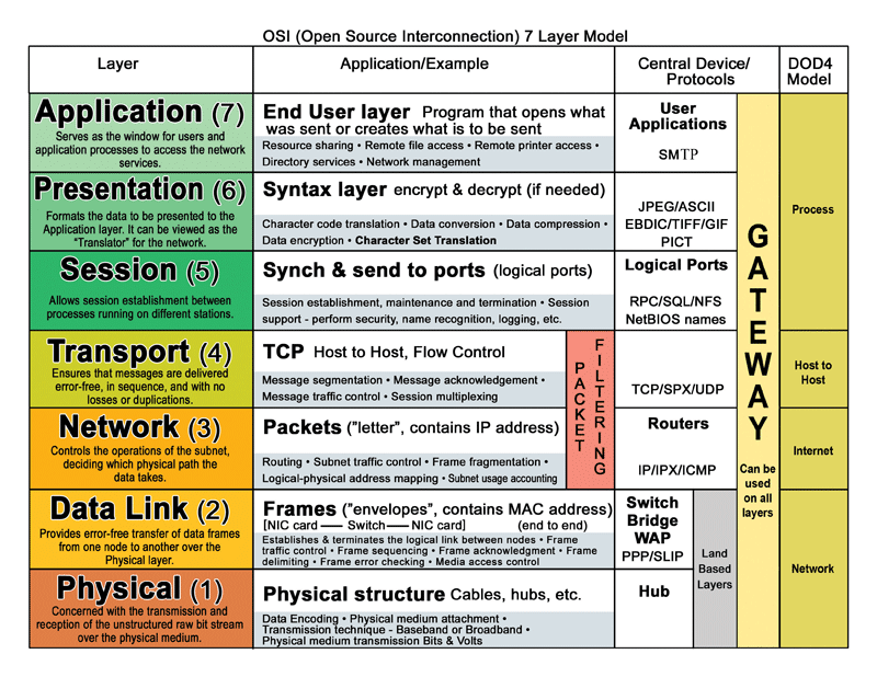
Each OSI layer contains a set of functions performed by programs to enable data to travel from a source to a destination on a network.
In this article I will provide brief descriptions of each layer in the OSI reference model.
Application Layer
The application layer is the OSI layer that is closest to the user. This layer provides network services to the user's applications. It differs from the other layers in that it does not provide services to any other OSI layer, but only to applications outside the OSI reference model. Applications layer provide a platform to access the data of remote computer.
The application layer protocols that you should know are as follows:
presentation layer
The presentation layer is responsible for formatting data so that application-layer protocols (and then the users) can recognize and work with it. Presentation layer format the file extensions—such as .doc, .jpg, .txt, .avi, and so on. you realize that each of these file types is formatted for use by a particular type of application. The presentation layer taking the application layer data and marking it with the formatting codes so that it can be viewed reliably when accessed later. If necessary, the presentation layer might be able to translate between multiple data formats by using a common format.
The Session Layer
The session layer establishes, manages, and terminates sessions between two communicating hosts. It provides its services to the presentation layer. The session layer also synchronizes dialogue between the presentation layers of the two hosts and manages their data exchange. For example, web servers have many users, so many communication processes are open at a given time. Therefore, keeping track of which user communicates on which path is important.
Transport Layer
Transport Layer
He transport layer is possibly the most important layer for exam study purposes. A lot is going on here, and it is heavily tested.
The transport layer's main jobs
Transport layer use two protocols for sending data TCP and UDP.
TCP
TCP is connection oriented protocols. Connection-oriented transmission is said to be reliable. Thinks TCP as registry AD facility available in Indian post office. For this level of service, you have to buy extra ticket and put a bunch of extra labels on it to track where it is going and where it has been. But, you get a receipt when it is delivered, you are guaranteed delivery, and you can keep track of whether your shipment got to its destination. All of this costs you more—but it is reliable!
UDP
UDP is connection less protocols. Connection-less transmission is said to be unreliable. Now, don't get too wrapped up in the term "unreliable" this doesn't mean that the data isn't going to get there; it only means that it isn't guaranteed to get there. Think of your options when you are sending a postcard, put it in the mailbox, and chances are good that it will get where it's supposed to go—but there is no guarantee, and stuff does go missing once in a while. On the other hand, it's cheap.
The transport layer can use two basic flow control methods:
There are two problems with the use of ready/not ready signals to implement flow control.
First, the destination may respond to the source with a not ready signal when its buffer fills up. While this message is on its way to the source, the source is still sending information to the destination, which the destination will probably have to drop because its buffer space is full.
The second problem with the use of these signals is that once the destination is ready to receive more information, it must first send a ready signal to the source, which must receive it before more information can be sent.In many implementations, the window size is dynamically negotiated up front and can be renegotiated during the lifetime of the connection.
In windowing a window size is defined between two host engaged in data transmission. And sender host will wait for an acknowledgement signal after sending the segments equal to window size. If any packet lost in way receiver will respond with acknowledgement for lost packet. And sender will send lost packet again.
Reliability
When reliability is necessary, it should cover these four items:
Connection Multiplexing/Application Mapping
Transport layer assigns a unique set of numbers for each connection. These numbers are called port or socket numbers. TCP, and UDP, provide a multiplexing function for a device: This allows multiple applications to simultaneously send and receive data.
Imagine a server that performs a number of functions—for example email, web pages, FTP, and DNS. The server has a single IP address, but can perform all these different functions for all the hosts that want to connect to it. The transport layer (layer 4) uses port numbers to distinguish between different types of traffic that might be headed for the same IP address.
Port numbers are divided into ranges by the IANA. Following are the current port ranges:
| Port number | descriptions |
0–1023
|
Well-Known—For common TCP/IP functions and applications
|
1024–49151
|
Registered—For applications built by companies
|
49152–65535
|
Dynamic/Private—For dynamic connections or unregistered applications
|
Common TCP and UDP Port Numbers
| TCP | UDP | ||
| FTP | 20, 21 | DNS | 53 |
| Telnet | 23 | DHCP | 67,68 |
| SMTP | 25 | TFTP | 69 |
| DNS | 53 | NTP | 123 |
| HTTP | 80 | SNMP | 161 |
| POP | 110 | ||
| NNTP | 119 | ||
| HTTPS | 443 | ||
Network Layer
The network layer provides a logical topology and layer-3 addresses. Routers function at the network layer. This layer is responsible for three main functions:
IP packet
Where the transport layer uses segments to transfer information between machines, the Internet layer uses datagram's. Datagram is just another word for packet.
The IP protocol is mainly responsible for these functions:
IP addresses are broken into two components:
Two types of packets are used at the Network layer: data and route updates.
Data packets
Used to transport user data through the internetwork. Protocols used to support data traffic are called routed protocols; examples of routed protocols are IP and IPv6.
Route update packets
Used to update neighboring routers about the networks connected to all routers within the internetwork. Protocols that send route update packets are called routing protocols; examples of some common ones are RIP, RIPv2, EIGRP, and OSPF. Route update packets are used to help build and maintain routing tables on each router.
IP Classes
Class A addresses range from 1-126: 00000001-01111111.
- 0 is reserved and represents all IP addresses;
- 127 is a reserved address and is used for testing, like a loop back on an interface:
- 255 is a reserved address and is used for broadcasting purposes.
Public addresses are Class A, B, and C addresses that can be used to access devices in other public networks, such as the Internet. Public IP address assign authority The Internet Assigned Numbers Authority (IANA) is ultimately responsible for handing out and managing public addresses. Normally you get public addresses directly from your ISP, which, in turn, requests them from one of five upstream address registries:
Private IP and ISP
Private ip address can be used to configure private network. You can use private ip to build your network without paying a single rupees. But one biggest problem with private ip is that with private you can not access the internet. This is the point where ISP comes from. ISP purchase a bulk of public ip address and provide them on rent. Whatever you pay to ISP for accessing internet is actually the charge of using public ip address.
Private ip address:- Not route able in public network
| Protocol | Description |
| IP |
IP of TCP/IP, featuring routable 32-bit addressing.
|
| IPX |
The equivalent of IP in Novell Netware.
|
| ICMP |
Internet Connection Management Protocol. Incorporates Ping and Traceroute, which are layer 3 link-testing utilities.
|
| OSPF, IGRP, EIGRP, RIP, ISIS |
Dynamic routing protocols that learn about remote networks and the best paths to them from other routers running the same protocol.
|
| ARP, RARP |
Address Resolution Protocol (and Reverse ARP). ARP learns what MAC address is associated with a given IP address. Reverse ARP learns an IP address given a MAC address.
|
Data link layer
Main functions of data link layer is
There are two specifications of Ethernet frame Ethernet II and 802
802.2 use a SAP or SNAP field to differentiate between encapsulatedlayer-3 payloads.
With a SNAP frame, the SAP fields are set to 0xAA and the type field is used to indicate the layer-3 protocol. One of the issues of the original SAP field in the 802.2 SAP frame is that even though it is eight bits (one byte) in length, only the first six bits are used for identifying upper-layer protocols, which allows up to 64 protocols.
802.2 SNAP frame support of up to 65,536 protocols
Ethernet II's Version of Ethernet
Physical Layer
The Physical layer communicates directly with the various types of actual communication media. Different kinds of media represent these bit values in different ways. Some use audio tones, while others utilize state transitions—changes in voltage from high to low and low to high. Specific protocols are needed for each type of media to explain the proper bit patterns to be used, how data is encoded into media signals, and the various qualities of the physical media’s attachment interface.
Fiber Cabling
Two types of fiber are used for connections: multimode and single-mode.
Multimode fiber
has a fiber thickness of either 850 or 1300 nanometers (nm), and the light signal is typically provided by an LED. When transmitting a signal, the light source is bounced off of the inner cladding (shielding) surrounding the fiber. Multimode fiber can achieve speeds in the hundreds of Mbps range, and many signals can be generated per fiber.
Single-mode fiber
has a fiber thickness of 1300 or 1550 nm and uses a laser as the light source. Because lasers provide a higher output than LEDs, single-mode fiber can span over 10 kilometers and have speeds up to 100Gbps. With single-mode fiber, only one signal is used per fiber.
Two main standards are used to describe the transmission of signals across a fiber:
SONET is defined by the Exchange Carriers Standards Association (ECSA) and American National Standards Institute (ANSI) and is typically used in North America.
SDH is an international standard used throughout most of the world (with the exception of North America). Both of these standards define the physical layer framing used to transmit light sources, which also includes overhead for the transmission
Core Layer
The core provides a high-speed layer-2 switching infrastructure and typically does not manipulate packet contents.
Distribution Layer
The distribution layer provides a boundary between the access and core layers. It contains routers and switches. Routers are used to provide the logical boundary--broadcasts are contained within the access layer and Filtering policies can be implemented to restrict traffic flows.
Access Layer
The access layer provides the user's initial access to the network, which is typically via switches or hubs.
TCP/IP protocol
The TCP/IP protocol stack has four layers. Note that although some of the layers in the TCP/IP protocol stack have the same names as layers in the OSI reference model, the layers have different functions in each model, as is described in the following list:
Application layer:
The application layer handles high-level protocols, including issues of representation, encoding, and dialog control. The TCP/IP model combines all application-related issues into one layer and ensures that this data is properly packaged for the next layer.
Transport layer:
The transport layer deals with QoS issues of reliability, flow control, and error correction. One of its protocols, TCP, provides for reliable network communications.
Internet layer:
The purpose of the Internet layer is to send source datagrams from any network on the internetwork and have them arrive at the destination, regardless of the path they took to get there.
Network access layer:
The name of this layer is broad and somewhat confusing. It is also called the host-to-network layer. It includes the LAN and WAN protocols and all the details in the OSI physical and data link layers.


0 komentar:
Post a Comment